
TM 5-2420-231-23-2
0224
REMOVAL CONTINUED
NOTE
The procedure for the removal and replacement of the brake clevis is identical for left-
hand and right-hand brake master cylinders. Left-hand brake clevis is shown in this
procedure.
Note location of brake clevis and jamnut to aid in installation.
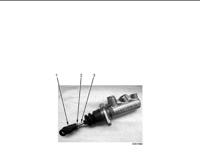
26. Loosen jamnut (Figure 6, Item 2) on master cylinder rod (Figure 6, Item 3).
27. Remove brake clevis (Figure 6, Item 1) from master cylinder rod (Figure 6, Item 3).
28. Remove jamnut (Figure 6, Item 2) from master cylinder rod (Figure 6, Item 3).
Figure 6. Master Cylinder Clevis.
0224
END OF TASK
CLEANING AND INSPECTION
0224
Clean and inspect all parts IAW Mechanical General Maintenance Instructions (WP 0369).
END OF TASK