
TM 5-2420-231-23-2
0224
INSTALLATION
0224
NOTE
The procedure for brake clevis removal and replacement of the brake clevis is identical for
left-hand and right-hand brake master cylinders. Left-hand brake clevis is shown in this
procedure.
Install jamnut and brake clevis as noted during removal.
Remove plugs and caps from hoses and fittings.
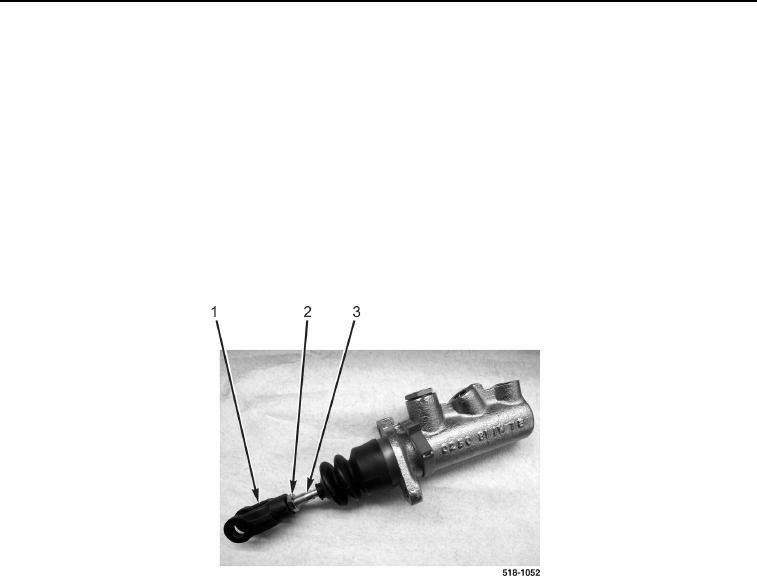
1. Install jamnut (Figure 7, Item 2) on master cylinder rod (Figure 7, Item 3).
2. Install brake clevis (Figure 7, Item 1) on master cylinder rod (Figure 7, Item 3) as noted during disassembly.
3. Tighten jamnut (Figure 7, Item 2) against master cylinder rod (Figure 7, Item 3).
Figure 7. Master Cylinder Clevis.
0224