
TM 5-2420-231-23-2
0224
BLEEDING BRAKE SYSTEM CONTINUED
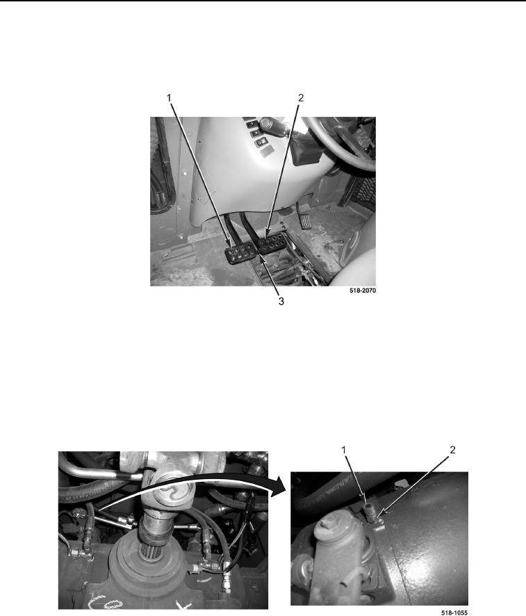
5. Pull pin (Figure 14, Item 3) to separate brake pedals.
6. With assistance, hold left brake pedal (Figure 14, Item 1) down half way, and pump right brake pedal
(Figure 14, Item 2) four times. Do not release right pedal.
Figure 14. Brake Pedals.
0224
7. With assistance, remove dust cap (Figure 15, Item 1) from right brake bleeder (Figure 15, Item 2).
8. Open right brake bleeder (Figure 15, Item 2), and allow air to escape brake bleeder. Close right brake bleeder.
9. Repeat steps 5 through 7 until no air is present in hydraulic fluid.
10. Install dust cap (Figure 15, Item 1) on right brake bleeder (Figure 15, Item 2).
11. Repeat steps 2 through 4.
Figure 15. Right Brake Bleeder.
0224