• Home
  • Download PDF
  • Order CD-ROM
  • Order in Print
Figure 10. Hydraulic Hoses.
Figure 13. Drive Shaft.

Tractor, Wheeled, Industrial Backhoe Loader Nsn 2420-01-532-3399
Page Navigation
  10    11    12    13    14  15  16    17    18    19    20  
img
.
TM 5-2420-231-23-3
0230
INSTALLATION CONTINUED
8. Remove sling from hydraulic oil pump.
9. Position wiring harness (Figure 11, Item 1) on machine.
NOTE
Install tiedown straps as noted during removal.
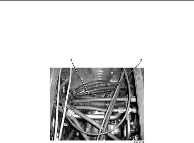
10. Install new tiedown straps (Figure 11, Item 2) on wiring harness (Figure 11, Item 1).
Figure 11. Tiedowns.
0230
0230-11


Privacy Statement
Press Release
Contact

© Copyright Integrated Publishing, Inc.. All Rights Reserved.