
TM 5-2420-231-23-3
0230
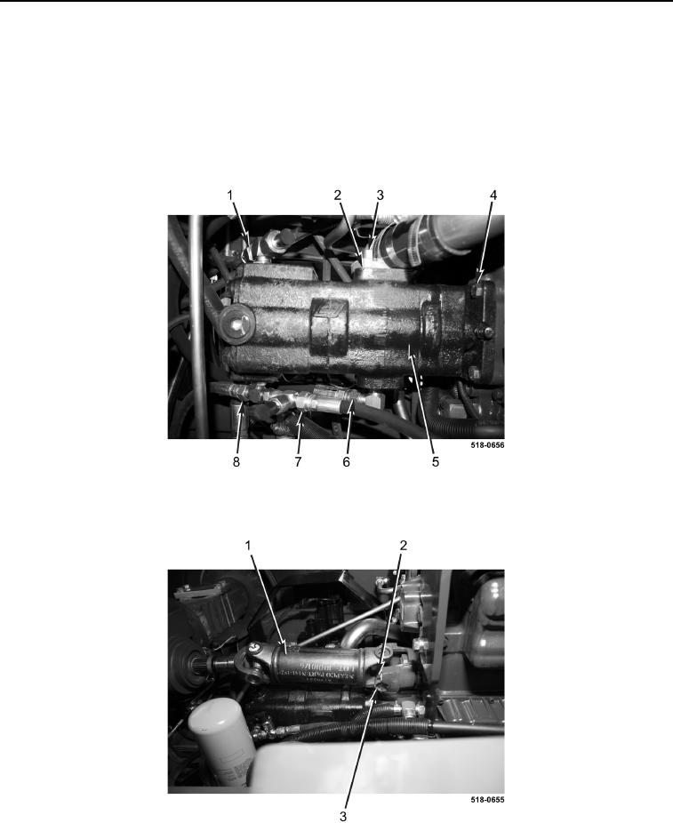
INSTALLATION CONTINUED
11. Install two bolts (Figure 12, Item 4) on hydraulic oil pump (Figure 12, Item 5).
12. Install bolt (Figure 12, Item 2) on flange (Figure 12, Item 3).
13. Connect quick-coupler (CF) hose (Figure 12, Item 8) on hydraulic oil pump (Figure 12, Item 5).
14. Connect pressure hose (Figure 12, Item 6) on hydraulic oil pump (Figure 12, Item 5).
15. Connect steering (CF) hose (Figure 12, Item 7) on hydraulic oil pump (Figure 12, Item 5).
16. Connect pressure (EF) hose (Figure 12, Item 1) on hydraulic oil pump (Figure 12, Item 5).
Figure 12. Hydraulic Hoses.
0230
17. Install drive shaft (Figure 13, Item 1), two collars (Figure 13, Item 3), and four bolts (Figure 13, Item 2) on
machine.
Figure 13. Drive Shaft.
0230
END OF TASK