
TM 5-2420-231-23-3
0232
REMOVAL CONTINUED
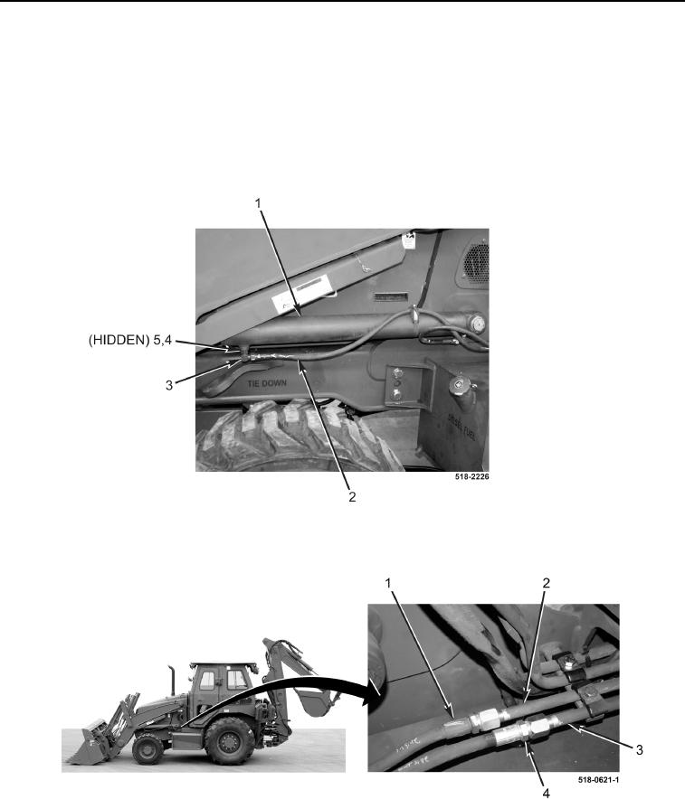
7. Disconnect two hoses (Figure 6, Item 2) from loader lift cylinder (Figure 6, Item 1).
NOTE
Note position and orientation of cylinder fittings to aid in installation.
8. Loosen two nuts (Figure 6, Item 4) and remove two fittings (Figure 6, Item 3) and O-rings (Figure 6, Item 5)
from loader lift cylinder (Figure 6, Item 1). Discard O-rings.
Figure 6. Cylinder.
0232
9. Disconnect two hoses (Figure 7, Items 1 and 4) from tubes (Figure 7, Items 2 and 3) and remove hoses from
machine.
Figure 7. Hoses.
0232
10. Repeat steps 6 through 9 for right-side loader lift cylinder hydraulic hoses.
END OF TASK