
TM 5-2420-231-23-3
0232
INSTALLATION CONTINUED
NOTE
Install fittings in position and orientation noted during removal.
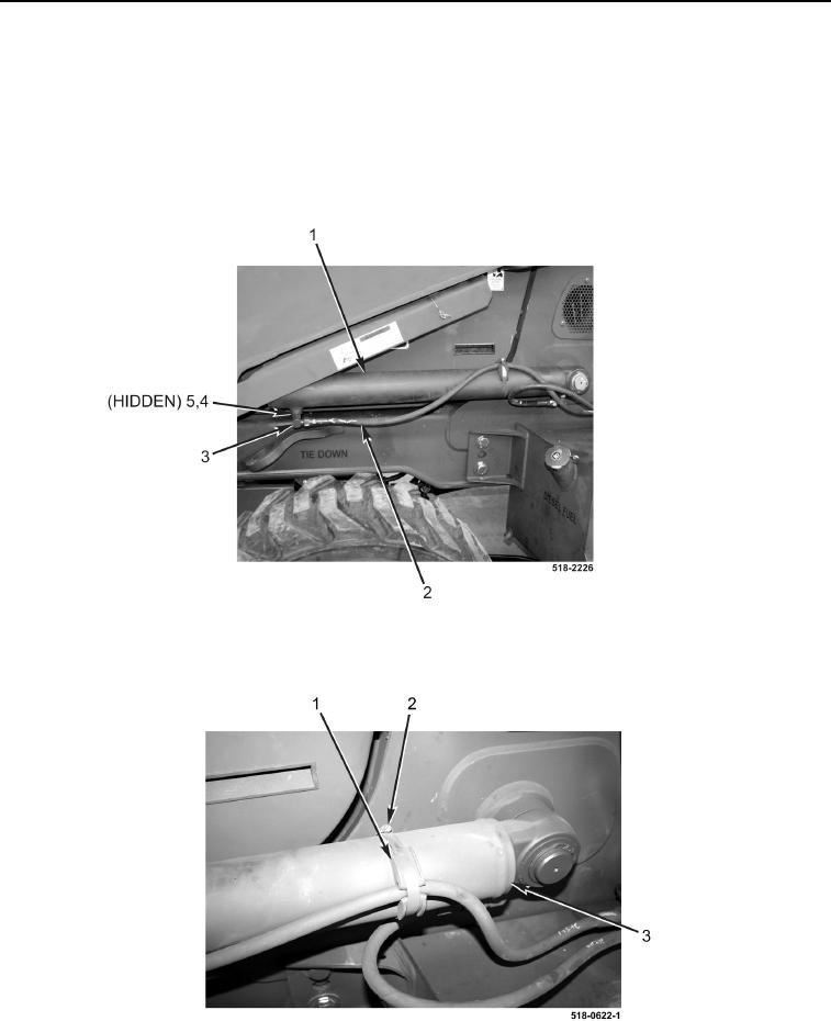
2. Install two new O-rings (Figure 9, Item 5) and fittings (Figure 9, Item 3) on loader lift cylinder (Figure 9, Item 1)
and tighten nuts (Figure 9, Item 4).
3. Connect two hoses (Figure 9, Item 2) to loader lift cylinder (Figure 9, Item 1).
Figure 9. Cylinder.
0232
4. Install resilient mount (Figure 10, Item 1) and clamp (Figure 10, Item 2) on cylinder (Figure 10, Item 3).
Figure 10. Clamp.
0232
5. Repeat steps 1 through 4 for right-side loader lift cylinder hydraulic hoses.