
TM 5-2420-231-23-3
0260
INSTALLATION
0260
WARNING
Hydraulic oil is very slippery. Immediately wipe up any spills. Failure to follow this warning
may result in injury or death to personnel.
NOTE
Remove plugs and caps from hoses and fittings.
Install lines as tagged and marked during removal.
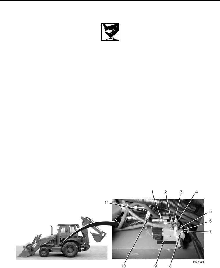
1. Position loader tool and backhoe coupler solenoid valve assembly (Figure 4, Item 2) on machine.
2. Connect two hydraulic hoses (Figure 4, Item 1) to loader tool and backhoe coupler solenoid valve assembly
(Figure 4, Item 9).
3. Install loader tool and backhoe coupler solenoid valve assembly (Figure 4, Item 9), three washers (Figure 4,
Item 8), and nuts (Figure 4, Item 7) on bolts (Figure 4, Item 6).
4. Connect hydraulic hose (Figure 4, Item 1) to loader tool and backhoe coupler solenoid valve assembly
(Figure 4, Item 9).
5. Connect hydraulic hose (Figure 4, Item 2) to loader tool and backhoe coupler solenoid valve assembly
(Figure 4, Item 9).
6. Connect hydraulic hose (Figure 4, Item 4) to loader tool and backhoe coupler solenoid valve assembly
(Figure 4, Item 9).
7. Connect hydraulic hose (Figure 4, Item 3) to loader tool and backhoe coupler solenoid valve assembly
(Figure 4, Item 9).
8. Connect hydraulic hose (Figure 4, Item 5) to loader tool and backhoe coupler solenoid valve assembly
(Figure 4, Item 9).
9. Connect three solenoid connectors (Figure 4, Item 10) to wiring harness (Figure 4, Item 11).
Figure 4. Loader Tool and Backhoe Coupler Solenoid Valve Assembly.
0260