
TM 5-2420-231-23-3
0292
REMOVAL CONTINUED
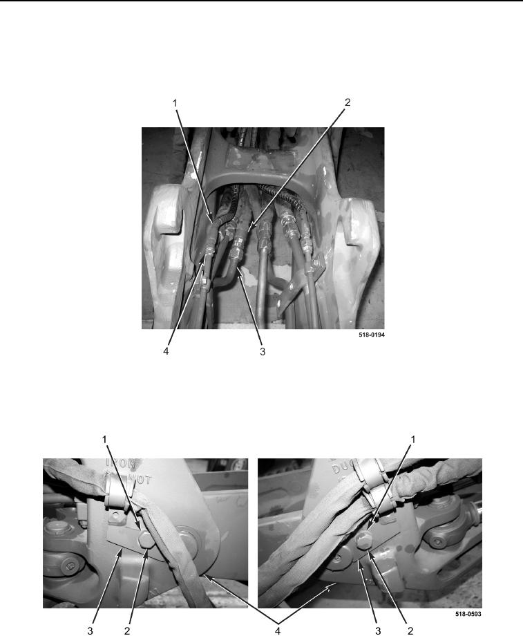
5. Disconnect two hoses (Figure 5, Item 1) from tubes (Figure 5, Item 4).
6. Disconnect six hoses (Figure 5, Item 2) from tubes (Figure 5, Item 3).
7. Remove two tubes (Figure 5, Items 4) and six tubes (Figure 5, Item 3) from backhoe boom arm.
Figure 5. Backhoe Boom Arm Hydraulic Connections.
0292
8. Remove two bolts (Figure 6, Item 2), washers (Figure 6, Item 1), and pin locks (Figure 6, Item 3) from swing
tower (Figure 6, Item 4).
Figure 6. Backhoe Boom Arm Pin Locks.
0292