
TM 5-2420-231-23-3
0292
CLEANING AND INSPECTION
0292
Clean and inspect all parts IAW Mechanical General Maintenance Instructions (WP 0369).
END OF TASK
INSTALLATION
0292
WARNING
Use extreme caution when handling heavy parts. Provide adequate support and use
assistance during procedure. Ensure any lifting device used is in good condition and of
suitable load capacity. Keep clear of heavy parts supported only by lifting device. Failure
to follow this warning may result in injury or death to personnel.
NOTE
Boom arm weighs 966 lb (440 kg).
Remove plugs and caps from hoses and fittings.
Install lines as tagged and marked during removal.
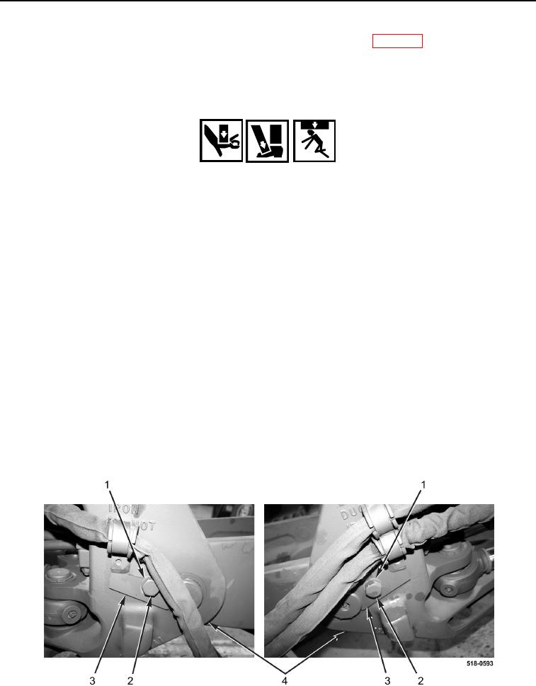
1. Attach sling and lifting device to backhoe boom arm (Figure 7, Item 4).
2. Lightly grease two backhoe boom arm pins (Figure 7, Item 3).
NOTE
Install backhoe boom arm shims in location and quantity noted during removal.
3.
Using lifting device, install backhoe boom arm (Figure 7, Item 4), shims (Figure 7, Item 2), and two backhoe
boom arm pins (Figure 7, Item 3) on swing tower (Figure 7, Item 1).
4. Install two pin locks (Figure 8, Item 3), washers (Figure 8, Item 1), and bolts (Figure 8, Item 2) on swing tower
(Figure 8, Item 4).
5. Lower boom arm (Figure 7, Item 4) onto trestle.
6. Remove sling and lifting device from boom arm (Figure 7, Item 4).
Figure 8. Bracket and Bolt.
0292