
TM 5-2420-231-23-3
0300
FRONT CHASSIS MOUNTS INSTALLATION CONTINUED
NOTE
The procedure for front bracket link installation is identical for left-hand and right-hand
front bracket links. Left-hand front bracket link is shown in this procedure.
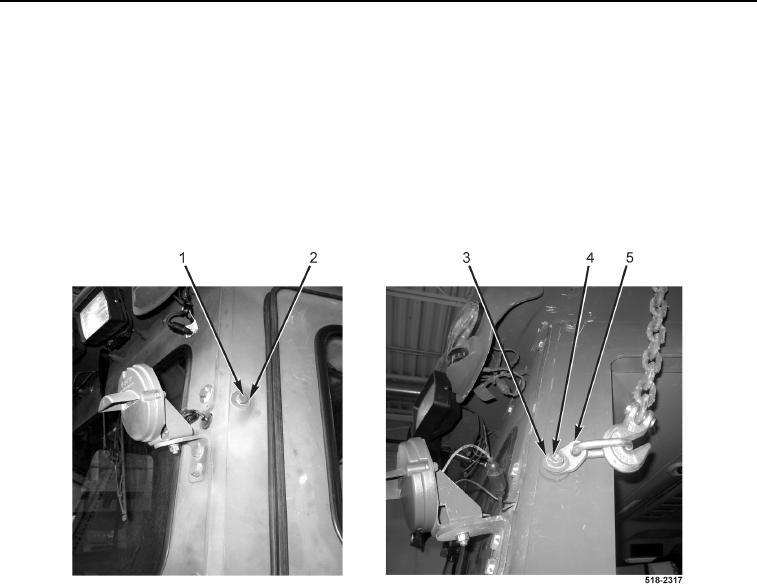
9. Remove two lift chains and lifting device from two bracket links.
10. Remove bolt (Figure 8, Item 4), washer (Figure 8, Item 3), and bracket link (Figure 8, Item 5) from cab.
11. Install washer (Figure 8, Item 2) and bolt (Figure 8, Item 1) on cab.
12. Repeat steps 10 and 11 for right-hand front bracket link.
Figure 8. Lifting Device.
0300
END OF TASK