
TM 5-2420-231-23-3
0300
FRONT CHASSIS MOUNTS INSTALLATION CONTINUED
NOTE
The procedure for tube cover removal and replacement is identical for left-hand and right-
hand tube covers. Left-hand tube cover is shown in this procedure.
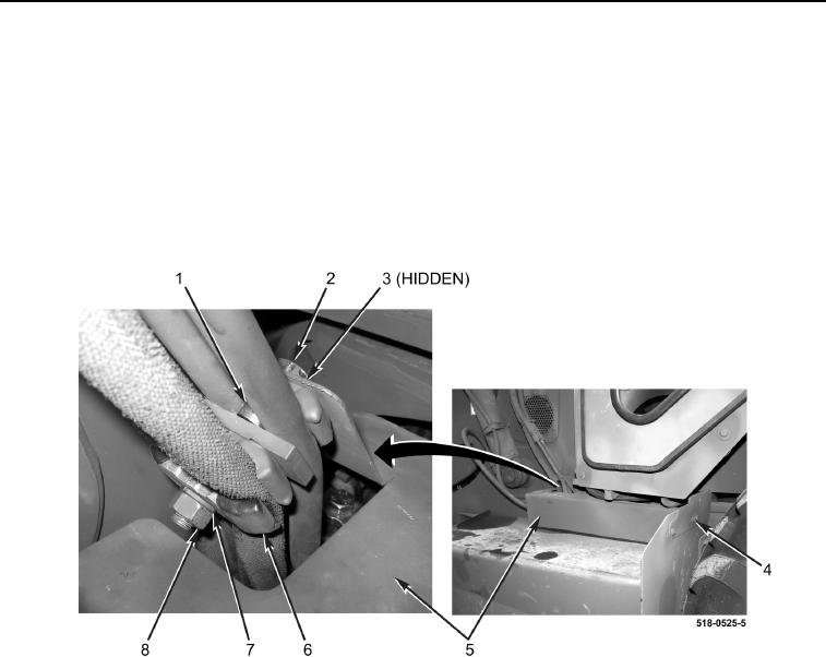
6. Install cover (Figure 7, Item 5), two spacers (Figure 7, Item 1), three clamps (Figure 7, Item 6), new lockwasher
(Figure 7, Item 7), washer (Figure 7, Item 3), bolt (Figure 7, Item 2), and nut (Figure 7, Item 8) on machine.
7. Install bolt (Figure 7, Item 4) on machine.
8. Repeat steps 6 and 7 for right-hand tube cover.
Figure 7. Tube Cover.
0300