
TM 5-2420-231-23-3
0301
REMOVAL CONTINUED
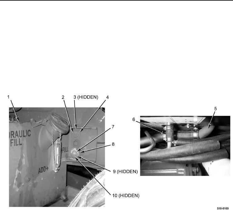
9. Remove bolt (Figure 8, Item 2), washer (Figure 8, Item 4), and spacer (Figure 8, Item 3) from hydraulic oil tank
(Figure 8, Item 1).
10. Remove bolt (Figure 8, Item 7), washer (Figure 8, Item 8), spacer (Figure 8, Item 9), hydraulic oil tank
(Figure 8, Item 1), and spacer (Figure 8, Item 10) from machine.
NOTE
Be sure to remove hydraulic oil tank horizontally while disconnecting return hose.
11. Disconnect return hose (Figure 8, Item 6) from hydraulic oil tank (Figure 8, Item 5).
12. Using lifting device and with assistance, lower battery box and hydraulic oil tank onto a flat surface.
13. Remove hydraulic oil tank from lifting device.
Figure 8. Hydraulic Oil Tank Bolts at Front of Battery Box.
0301
END OF TASK