
TM 5-2420-231-23-3
0301
DISASSEMBLY CONTINUED
NOTE
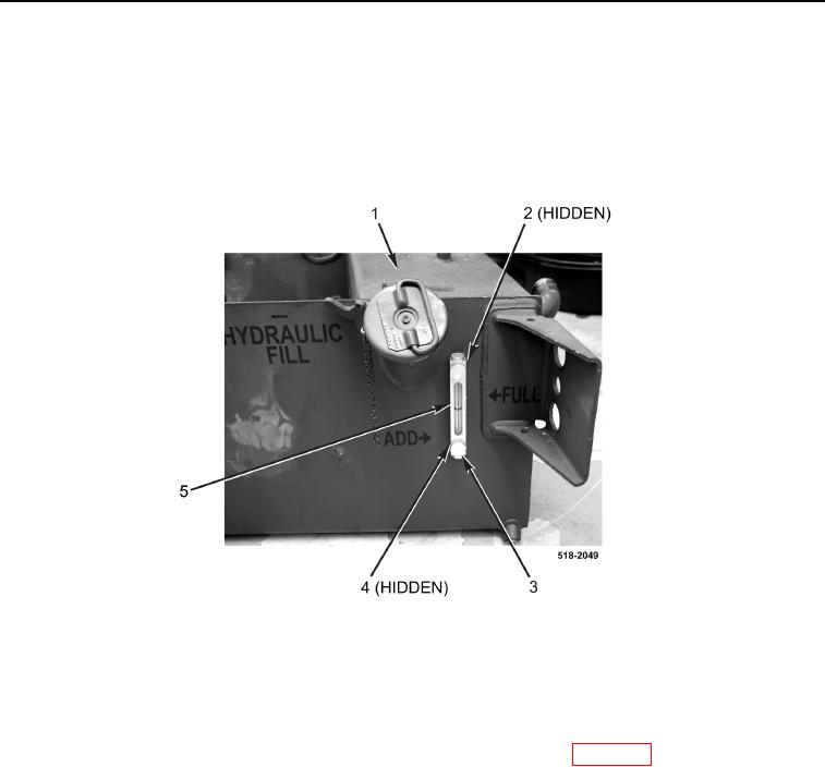
Note position and orientation of hydraulic oil level sight glass to aid in installation.
5. Remove two bolts (Figure 11, Item 3), O-rings (Figure 11, Item 4), hydraulic oil level sight glass (Figure 11,
Item 5) and two O-rings (Figure 11, Item 2) from hydraulic oil tank (Figure 11, Item 1). Discard O-rings.
Figure 11. Hydraulic Oil Level Sight Glass.
0301
END OF TASK
CLEANING AND INSPECTION
0301
Clean and inspect all parts IAW Mechanical General Maintenance Instructions (WP 0369).
END OF TASK