
TM 5-2420-231-23-3
0310
REMOVAL CONTINUED
NOTE
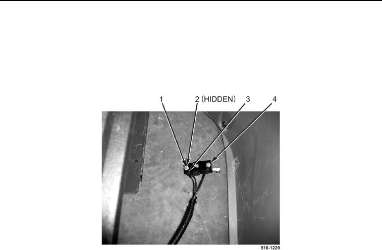
Tag and mark wires to aid in installation.
2. Remove two screws (Figure 2, Item 1), lockwashers (Figure 2, Item 2), and wires (Figure 2, Item 3) from switch
(Figure 2, Item 4). Discard lockwashers.
Figure 2. Switch Wire.
0310
NOTE
Note quantity and location of tiedown straps to aid in installation.
3. Remove tiedown strap (Figure 3, Item 1) from pedestal (Figure 3, Item 3) and switch wiring harness
(Figure 3, Item 2). Discard tiedown strap.
4. Remove four bolts (Figure 3, Item 4) and washers (Figure 3, Item 5) from pedestal (Figure 3, Item 3).