
TM 5-2420-231-23-3
0310
REMOVAL CONTINUED
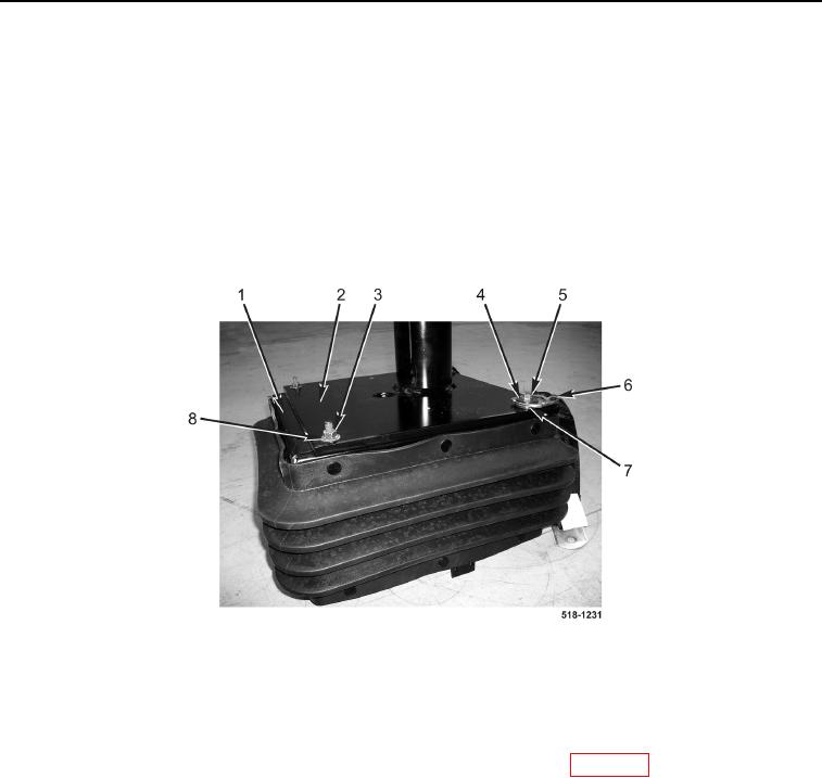
6. Remove two locknuts (Figure 4, Item 5), washers (Figure 4, Item 4), tethers (Figure 4, Item 6), and washers
(Figure 4, Item 7) from pedestal (Figure 4, Item 2). Discard locknuts.
7. Remove two locknuts (Figure 4, Item 3) and washers (Figure 4, Item 8) from pedestal (Figure 4, Item 2).
Discard locknuts.
NOTE
Note position and orientation of pedestal on seat support to aid in installation.
8. Remove pedestal (Figure 4, Item 2) from seat support (Figure 4, Item 1).
Figure 4. Pedestal Nuts.
0310
END OF TASK
CLEANING AND INSPECTION
0310
Clean and inspect all parts IAW Mechanical General Maintenance Instructions (WP 0369).
END OF TASK
INSTALLATION
0310
NOTE
Install pedestal on seat support in position and orientation noted during removal.
1. Install pedestal (Figure 4, Item 2) on seat support (Figure 4, Item 1).
2. Install two washers (Figure 4, Item 8) and new locknuts (Figure 4, Item 3) on pedestal (Figure 4, Item 2).
3. Install two washers (Figure 4, Item 7), tethers (Figure 4, Item 6), washers (Figure 4, Item 4), and new locknuts
(Figure 4, Item 5) on pedestal (Figure 4, Item 2).