
TM 5-2420-231-23-3
0327
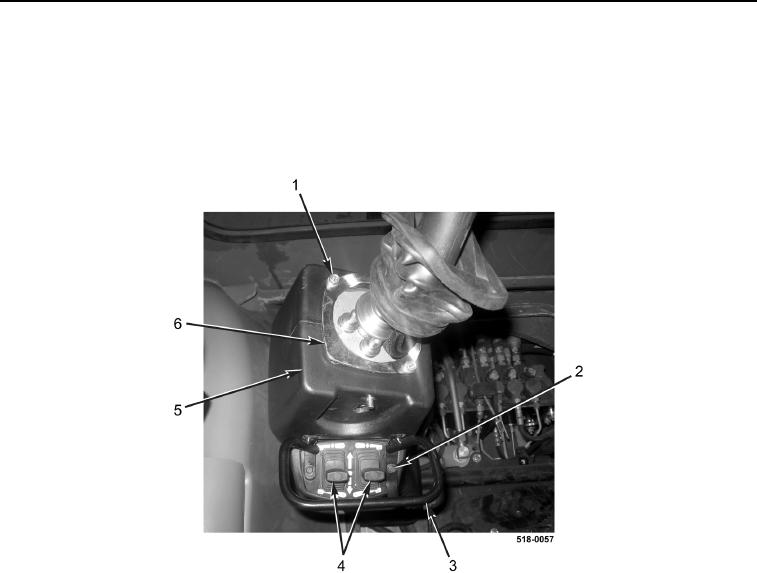
REMOVAL CONTINUED
24. Remove two bolts (Figure 12, Item 1) and retainer plate (Figure 12, Item 6) from left backhoe control tower
(Figure 12, Item 5).
25. Remove two bolts (Figure 12, Item 2) and switch guard (Figure 12, Item 3) from left backhoe control tower
(Figure 12, Item 5).
26. Remove stabilizer switches (Figure 12, Item 4) from left backhoe control tower (Figure 12, Item 5).
Figure 12. Stabilizer Switches.
0327
27. Disconnect two wiring harness connectors (Figure 13, Item 2) from stabilizer switch harness connectors
(Figure 13, Item 4).
28. Remove stabilizer switches (Figure 13, Item 4) from machine.
29. Route wiring harness connectors (Figure 13, Item 2) down into left backhoe control tower boot opening
(Figure 13, Item 1).
30. Remove left backhoe control tower boot (Figure 13, Item 3) from machine.