
TM 5-2420-231-23-3
0327
REMOVAL CONTINUED
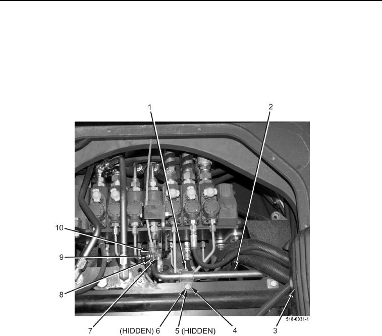
32. Remove cotter pin (Figure 15, Item 9) from boom latch cable clevis pin (Figure 15, Item 7). Discard cotter pin.
33. Remove clevis pin (Figure 15, Item 7), washer (Figure 15, Item 8), and boom latch cable clevis (Figure 15,
Item 10) from boom latch pedal rod (Figure 15, Item 2).
34. Remove two bolts (Figure 15, Item 4), lockwashers (Figure 15, Item 5), nuts (Figure 15, Item 6), and boom
latch pedal rod brackets (Figure 15, Item 1) from machine. Discard lockwashers.
35. Remove boom latch pedal rod (Figure 15, Item 2) and boot (Figure 15, Item 3) from machine.
Figure 15. Boom Latch Pedal Rod.
0327