
TM 5-2420-231-23-3
0327
REMOVAL CONTINUED
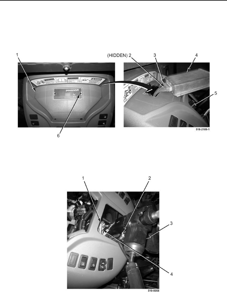
53. Remove two screws (Figure 24, Item 6) and powershift control module (Figure 24, Item 4) from cover
(Figure 24, Item 1).
54. Loosen bolt (Figure 24, Item 2) and disconnect wiring harness connector (Figure 24, Item 3) from powershift
control module (Figure 24, Item 4). Position powershift control module aside.
55. Remove cover (Figure 24, Item 1) from instrument panel (Figure 24, Item 5).
Figure 24. Powershift Control Module.
0327
56. Disconnect harness connector (Figure 25, Item 1) from connector (Figure 25, Item 4).
57. Disconnect harness connector (Figure 25, Item 2) from forward/neutral/reverse (FNR) switch
(Figure 25, Item 3).
Figure 25. FNR Switch Connection.
0327