
TM 5-2420-231-23-3
0327
REMOVAL CONTINUED
NOTE
Note quantity and location of tiedown straps for use in installation.
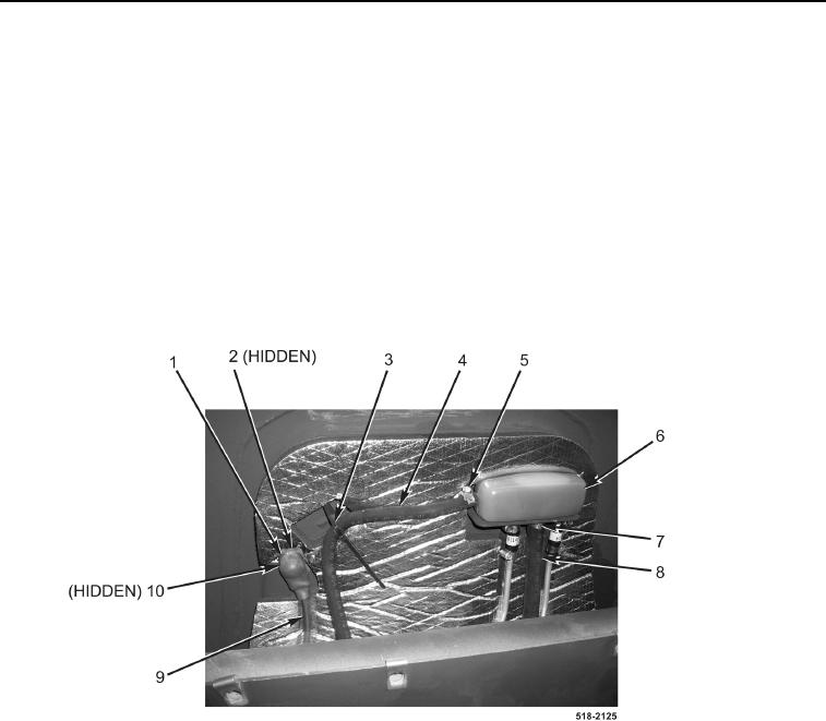
67. Remove tiedown straps (Figure 29, Item 3) from hose (Figure 29, Item 4). Discard tiedown straps.
68. Position boot (Figure 29, Item 1) aside.
69. Remove nut (Figure 29, Item 2) and power cable (Figure 29, Item 9) from bulkhead connector
(Figure 29, Item 10).
70. Loosen clamp (Figure 29, Item 7) and disconnect hose (Figure 29, Item 8) from brake master cylinder reservoir
(Figure 29, Item 6). Allow fluid to drain from hose and master cylinder reservoir.
71. Loosen clamp (Figure 29, Item 5) and disconnect hose (Figure 29, Item 4) from brake master cylinder reservoir
(Figure 29, Item 6).
Figure 29. Upper Front Bulkhead Connections.
0327