
TM 5-2420-231-23-3
0350
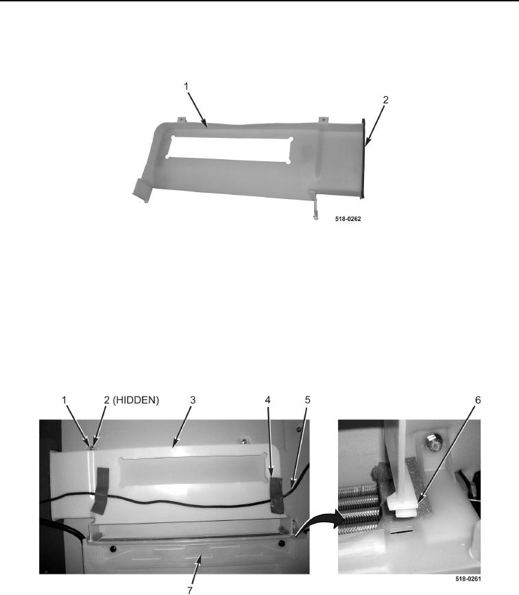
CLEANING AND INSPECTION CONTINUED
3. Inspect seal (Figure 9, Item 2) on filter tray (Figure 9, Item 1) for tears and damage. Remove seal if torn or
damaged.
Figure 9. Filter Tray Seal.
0350
END OF TASK
INSTALLATION
0350
1. Connect two locking tabs (Figure 10, Item 6) to main housing (Figure 10, Item 7) and install filter tray
(Figure 10, Item 3) on machine.
2. Install two washers (Figure 10, Item 2) and new locknuts (Figure 10, Item 1) on filter tray (Figure 10, Item 3).
3. Position wiring harness (Figure 10, Item 5) on filter tray (Figure 10, Item 3) with two new pieces of duct tape
(Figure 10, Item 4).
Figure 10. Filter Tray.
0350