
TM 5-2420-231-23-3
0360
REMOVAL CONTINUED
4. Lift evaporator (Figure 4, Item 1) from blower housing (Figure 4, Item 3).
5. Remove A/C temperature control tube (Figure 4, Item 2) from evaporator (Figure 4, Item 1).
Figure 4. A/C Temperature Control Tube.
0360
NOTE
Tag and mark wires to aid in installation.
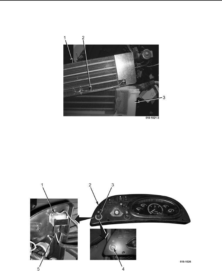
6. Disconnect two wires (Figure 5, Item 5) from temperature switch (Figure 5, Item 1).
7. Remove knob (Figure 5, Item 3) from control panel (Figure 5, Item 2).
8. Remove nut (Figure 5, Item 4) and temperature switch (Figure 5, Item 1) from control panel (Figure 5, Item 2).
Figure 5. A/C Temperature Switch.
0360
END OF TASK