
TM 5-3805-255-14
0020
MULTIMETER USAGE CONTINUED
NOTE
If digital readout will not zero properly, replace batteries and repeat zeroing procedure. If
digital readout will not zero after batteries have been replaced, notify your supervisor.
a. Zero the Multimeter.
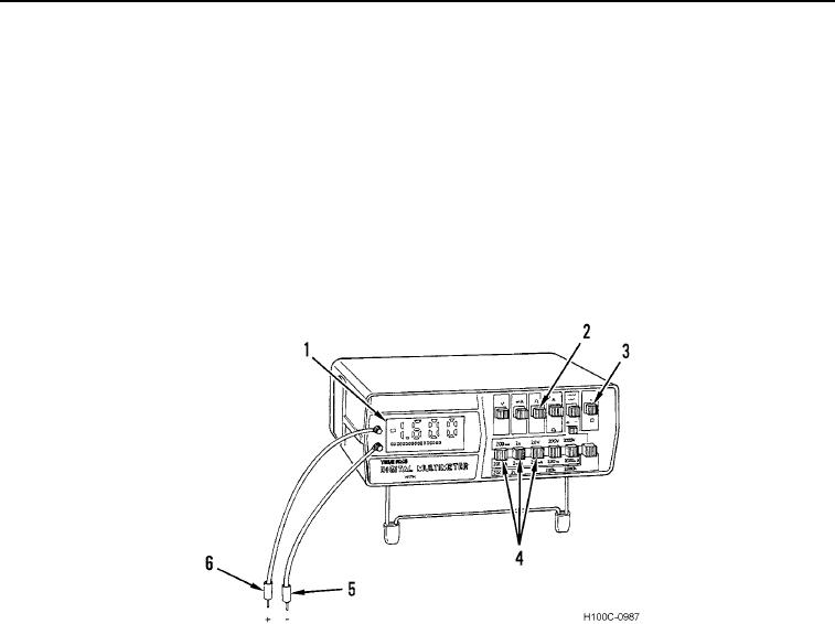
(1) Set multimeter ON/OFF switch (Figure 10, Item 3) to ON position.
(2) Press OHMS FUNCTION switch (Figure 10, Item 2).
(3) Press LOWEST VOLTAGE/OHMS selector switch (Figure 10, Item 4).
(4) Touch black and red probes (Figure 10, Items 5 and 6) together and check for a zero reading on digital
readout (Figure 10, Item 1).
Figure 10. Multimeter Usage.
0020
CAUTION
Before performing a continuity test, always disconnect batteries and circuit to be tested.
Failure to follow this caution may damage multimeter.
b. Testing for Continuity.
(1) Zero multimeter.
(2) Connect black and red probes (Figure 10, Items 5 and 6) from both terminals to circuit being tested.
(3) Read digital readout (Figure 10, Item 1) and interpret results as follows:
(a) If digital readout indicates 0L, circuit has continuity.
(b) If digital readout indicates resistance, circuit is open.
0020-10