
TM 5-3805-255-14
0020
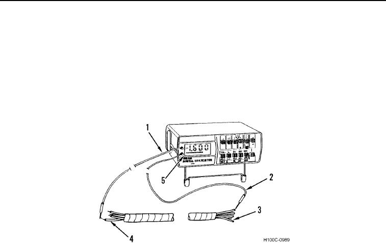
MULTIMETER USAGE CONTINUED
(1) Zero multimeter.
(2) Connect black probe (Figure 12, Item 2) to one circuit (Figure 12, Item 3) and red probe (Figure 12,
Item 1) to either a ground or another circuit (Figure 12, Item 4).
(3) Read digital readout (Figure 12, Item 5) and interpret results as follows:
(a) If digital readout indicates 0L, circuits are shorted or circuit is grounded if testing to ground.
(b) If digital readout does not indicate 0L, circuits are not shorted.
(c) If digital readout jumps or flickers, circuits are shorted or grounded intermittently.
Figure 12. Testing For Shorts.
0020
CAUTION
Before performing a continuity test, always disconnect batteries and circuit to be tested.
Failure to follow this caution may damage multimeter.
d. Testing for Resistance. Allowable resistance readings depend on circuit being tested. Refer to the partic-
ular section dealing with that circuit or component for allowable readings.
(1) Zero multimeter.
(2) Press OHMS FUNCTION switch (Figure 13, Item 3).
(3) Press LOWEST VOLTAGE/OHMS selector switch (Figure 13, Item 7). If test calls for ohms range other
than RX1, set RANGE SELECTOR switch (Figure 13, Item 6) to required range.
(4) Connect black and red probes (Figure 13, Items 8 and 9) across circuit to be tested.
(5) Read digital readout (Figure 13, Item 1) and interpret results as circuit resistance.
0020-12