
TM 5-3805-255-14
0020
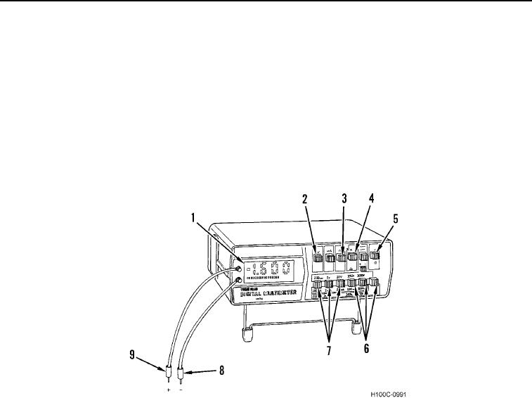
MULTIMETER USAGE CONTINUED
3. Measuring DC Voltage.
a. Set multimeter ON/OFF switch (Figure 13, Item 5) to ON position.
b. Press VOLTS FUNCTION switch (Figure 13, Item 2).
c.
Set AC/DC selector switch (Figure 13, Item 4) to DC.
d. Select and press LOWEST VOLTAGE/OHMS selector switch (Figure 13, Item 7) for voltage range higher
than volts to be measured.
e. Connect red probe (Figure 13, Item 9) to positive (+) side of circuit and black probe (Figure 13, Item 8) to
negative (-) side of circuit.
f.
Read digital readout (Figure 13, Item 1) and interpret results as DC voltage in circuit being tested.
Figure 13. Multimeter Usage.
0020
RELAY INSPECTION AND TEST
00020
1. Inspecting Relays.
a. Check for bent or damaged pins.
b. Check for burned or damaged relay case.
2. Testing Relays.
NOTE
When testing relays, always refer to the circuit diagram printed or stamped on relay case.
a. Using a multimeter, check for continuity across relay coil.
b. Using a multimeter, check open or closed contacts within relay.
END OF WORK PACKAGE
0020-13/(14 blank)