TM 5-3805-255-14
0028
ADJUSTMENT CONTINUED
NOTE
To verify that pump-to-engine timing is correct or incorrect, repeat steps 6 through 10 two
or three times to verify results.
11. Re-time pump-to-engine as follows:
a. Rotate engine crankshaft clockwise (as viewed from front) until No. 1 cylinder is coming up on
compression stroke and position engine vibration damper to 38 degree mark BTDC with last movement
made in direction of engine rotation. This will take up all slack in gear train.
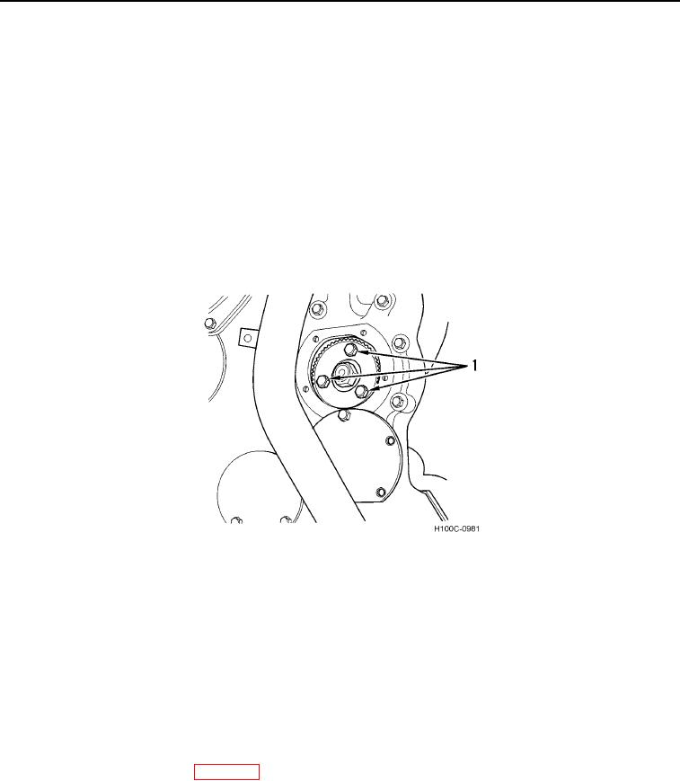
b. Loosen three drive gear retainer plate bolts (Figure 12, Item 1).
c.
Remove plug from top of pump adapter housing.
d. Rotate drive shaft to align timing pointer and timing mark on pump gear. Tighten three drive gear retainer
bolts (Figure 12, Item 1), replace cover and plug.
Figure 12. Injection Pump Timing Port in Crankcase Front Cover
0028
e. If drive shaft cannot be rotated to align pointer and mark within confines of three drive gear retainer plate
capscrew slots, injection pump must be removed. See Removal in this work package.
f.
Reinstall pump as described in steps 1 through 11 under INSTALLATION in this work package.
g. Repeat hydraulic method of checking port closure as previously outlined.
12. Remove drip tube and connect No. 1 fuel injection tube to delivery valve.
13. Disconnect wires securing governor control and shut-down levers.
14. Disconnect test pump and connect fuel line at pump inlet.
15. If it was necessary to re-time pump-to-engine as outlined in step 11, and timing was corrected; then complete
steps 13 through 22 under Installation in this work package.
16. Install engine access panels (WP 0005).
END OF TASK
END OF WORK PACKAGE
0028-14

