
TM 5-3805-255-14
0028
ADJUSTMENT CONTINUED
Low Idle Speed Adjustment -- Continued
00028
NOTE
Check to be sure that external pump control linkage travels 0.125 to 0.375 in. (3 to 9 mm)
beyond pump control lever with pin connecting linkage to pump lever removed, and
accelerator pedal or governor control lever is on its high idle stop screw.
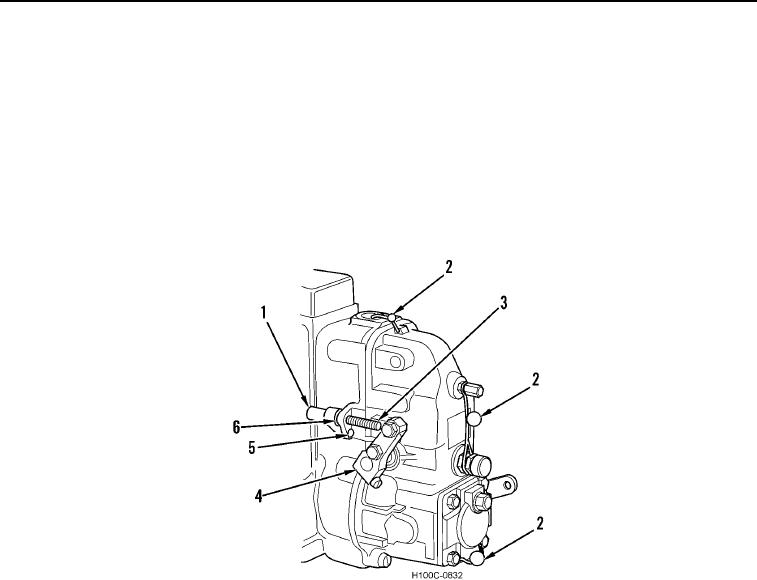
2. Install new seal cap (Figure 10, Item 1) over high idle adjustment screw (Figure 10, Item 5) and secure to boss
with new rivet (Figure 10, Item 5). Use seal pliers (Tool No. PLT-371-4) and seal rivet.
3. Install new seal wires (Figure 10, Item 2) and seal all adjustment points as shown in Figure 10.
Figure 10. Seal Wire Locations.
0028-11