
TM 5-3805-255-14
0053
INSTALLATION
00053
WARNING
Use extreme caution when handling heavy parts. Provide adequate support and use
assistance during procedure. Ensure that any lifting equipment is in good condition and of
suitable load capacity. Keep clear of heavy parts supported by lifting equipment. Failure to
follow this warning may result in injury or death to personnel.
1. Use a suitable lifting device to position planetary carrier assembly (Figure 6, Item 1) on front axle (Figure 6,
Item 2). As carrier is installed, planet gear teeth must mesh with ring gear teeth; large cut-out in carrier must be
aligned with cut-out in wheel hub.
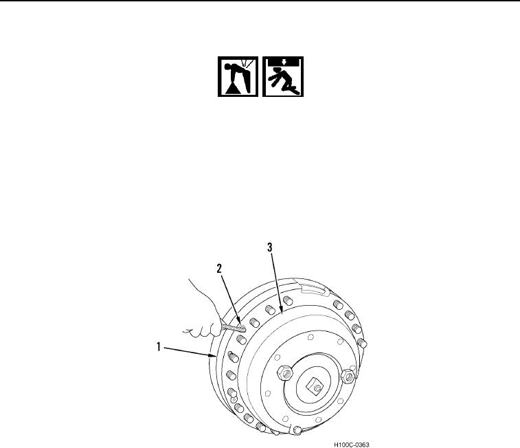
2. Install planetary carrier (Figure 6, Item 3) and install four flat head capscrews (Figure 6, Item 2) on wheel hub
(Figure 6, Item 1). Torque capscrews to 80 to 90 lb-ft (108 to 122 Nm).
Figure 6. Planetary Fastener Installation.
0053
0053-4