
TM 5-3805-255-14
0054
REMOVAL
00054
1. Jack up vehicle under rear differential until wheels are free of floor. Support vehicle using suitable support
stands placed under main frame.
2. Remove two wheels from rear axle.
3. Remove propeller shaft from rear axle (WP 0049).
4. Disconnect two brake lines from rear axle (WP 0058).
5. Support rear axle at each end with a suitable support stand. Position suitable lifting device under differential
bowl of axle.
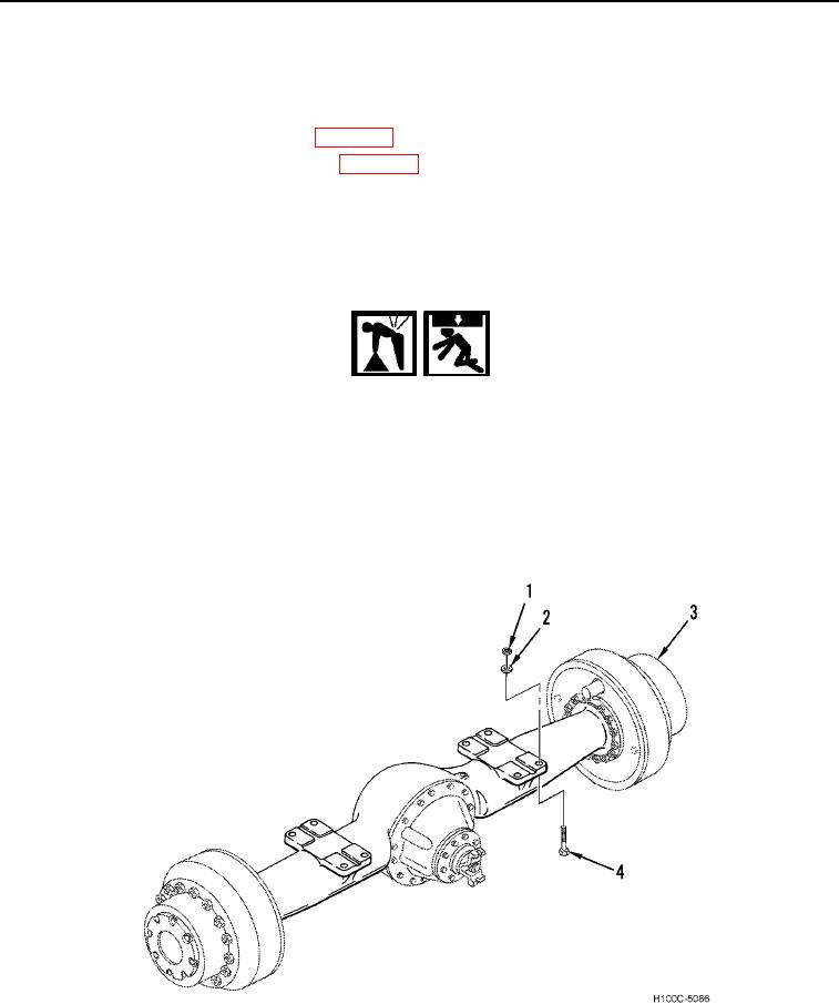
6. Remove eight bolts (Figure 1, Item 4), nuts (Figure 1, Item 1) and sixteen washers (Figure 1, Item 2) from axle
(Figure 1, Item 3) and bolster plate.
WARNING
Use extreme caution when handling heavy parts. Provide adequate support and use
assistance during the procedure. Ensure that any lifting equipment used is in good
condition and of suitable load capacity. Keep clear of heavy parts supported by lifting
equipment. Failure to follow this Warning may result in death or injury to personnel. In
event of injury, seek medical assistance.
7. Remove support stands from either end of rear axle. With assistance, lower rear axle on lifting device until it
clears underside of loader.
8. Remove rear axle from under loader.
Figure 1. Rear Axle.
0054
END OF TASK
0054-2