
TM 5-3805-255-14
0057
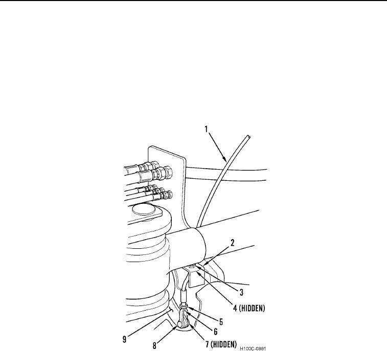
INSTALLATION CONTINUED
8. Install cable nut (Figure 4, Item 3) on cable (Figure 4, Item 1). Install cable (Figure 4, Item 1) through support
bracket (Figure 4, Item 2).
9. Install cable nut (Figure 4, Item 4) on cable (Figure 4, Item 1). Tighten two cable nuts.
10. Install clevis nut (Figure 4, Item 5) and cable end (Figure 4, Item 6) on cable (Figure 4, Item 1). Tighten clevis
nut.
11. Attach cable end (Figure 4, Item 6) to brake actuating arm (Figure 4, Item 9), aligning hole in arm with holes in
cable end. Install clevis pin (Figure 4, Item 8) through cable end and brake actuating arm.
12. Install new cotter pin (Figure 4, Item 7) on clevis pin (Figure 4, Item 8).
Figure 4. Parking Brake Linkage (Lower).
0057
END OF TASK
0057-5