
TM 5-3805-255-14
0057
ADJUSTMENT
00057
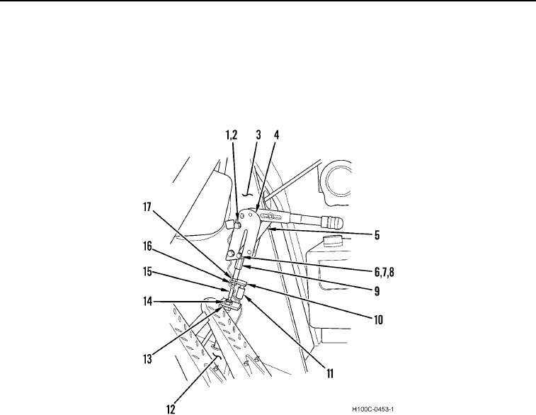
1. Turn adjustable top of brake handle (Figure 5, Item 4) counterclockwise to loosen; clockwise to tighten brake
shoes.
2. Adjust nuts (Figure 5, Items 16 and 17) so actuating plate (Figure 5, Item 10) is not in contact with warning
lamp switch. Ensure plate is in contact with warning lamp switch when handle is in down position.
3. Tighten all nuts after adjustment is complete.
Figure 5. Parking Brake Linkage (Upper).
0057
END OF TASK
END OF WORK PACKAGE
0057-6