
TM 5-3805-255-14
0057
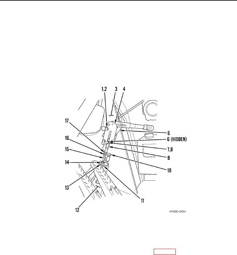
REMOVAL CONTINUED
7. Remove cotter pin (Figure 2, Item 6) and flat washer (Figure 2, Item 7) from pin (Figure 2, Item 8). Discard
cotter pin.
8. Remove pin (Figure 2, Item 8) and cable end (Figure 2, Item 9) from actuating arm (Figure 2, Item 5).
9. Remove two bolts (Figure 2, Item 1), washers (Figure 2, Item 2), and parking brake handle assembly (Figure 2,
Item 4) from sidewall of operator's compartment (Figure 2, Item 3).
10. Remove nut (Figure 2, Item 17), plate (Figure 2, Item 10) and nut (Figure 2, Item 16) from cable (Figure 2,
Item 15).
11. Remove cable nut (Figure 2, Item 14) and cable (Figure 2, Item 15) through bracket (Figure 2, Item 13).
12. Remove nut (Figure 2, Item 11) and cable (Figure 2, Item 15) through floorboard (Figure 2, Item 12).
Figure 2. Parking Brake Linkage (Upper).
0057
END OF TASK
CLEANING AND INSPECTION
00057
Clean and inspect all components IAW General Maintenance Instructions (WP 0019).
END OF TASK
0057-3