
TM 5-3805-255-14
0058
ASSEMBLY CONTINUED
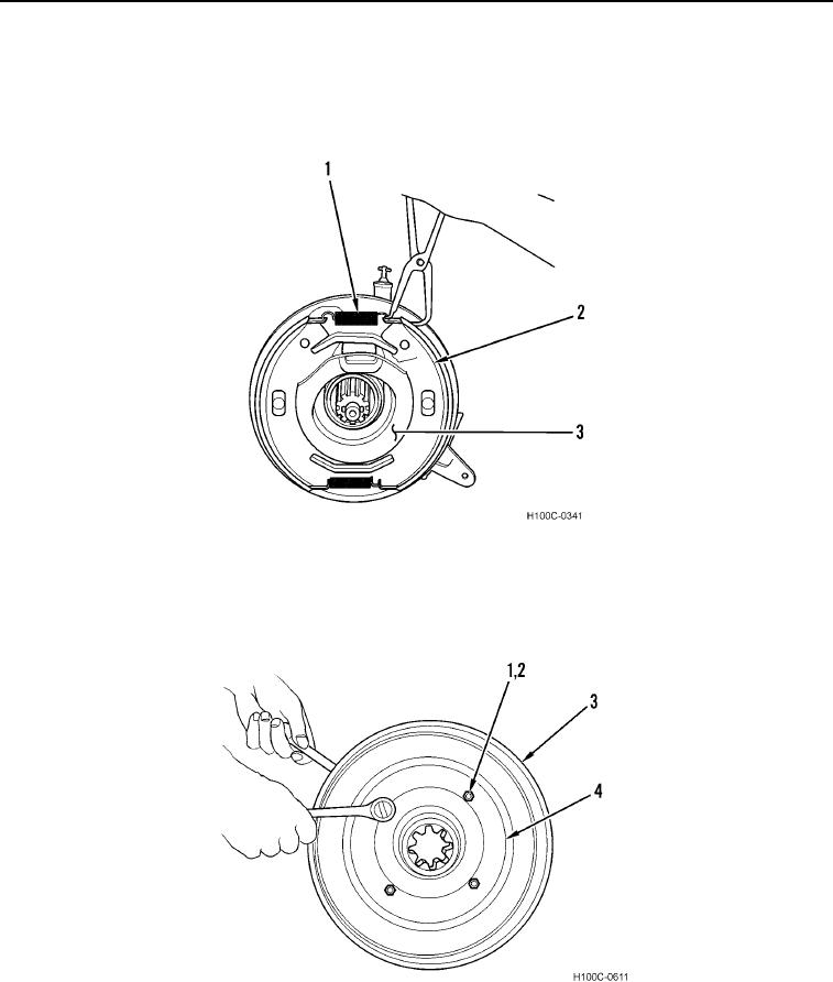
3. Install brake shoes (Figure 8, Item 2) on backing plate (Figure 8, Item 3).
4. Install brake springs (Figure 8, Item 1) on brake shoes (Figure 8, Item 2). Be sure springs are installed in rear
holes of brake shoes.
Figure 8. Brake Shoe.
0058
5. Install yoke (Figure 9, Item 4) in drum (Figure 9, Item 3) and install four bolts (Figure 9, Item 1) and new
lockwashers (Figure 9, Item 2). Tighten bolts to 36 lb-ft (48.8 Nm).
Figure 9. Drum Assembly.
0058
0058-7