TM 5-3805-255-14
0059
REMOVAL
00059
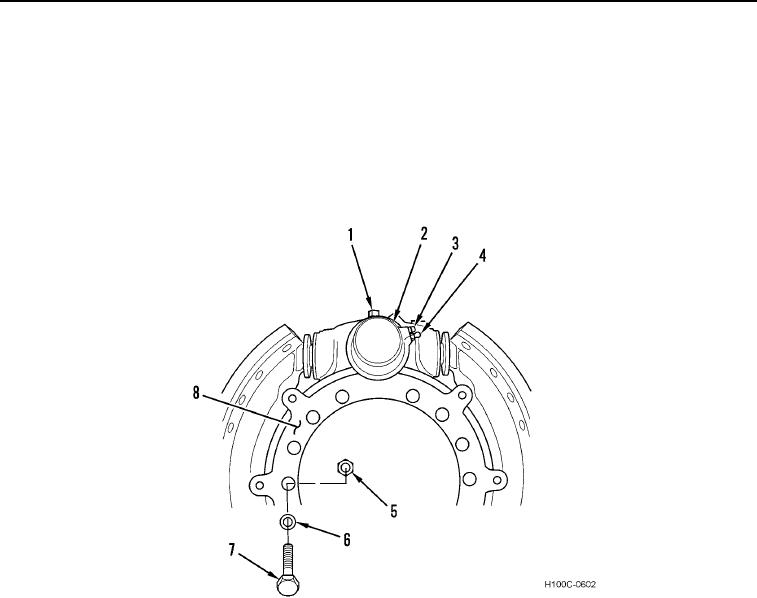
1. Disconnect hydraulic line (Figure 1, Item 4) from wheel cylinder (Figure 1, Item 2).
NOTE
Identify orientation of bolts for ease of installation.
2. Remove 15 bolts (Figure 1, Item 7), locknuts (Figure 1, Item 5), washers (Figure 1, Item 6), and spider
(Figure 1, Item 8) from axle.
Figure 1. Spider Assembly.
0059
END OF TASK
DISASSEMBLY
00059
1. Remove bleeder screw (Figure 1, Item 3) from wheel cylinder (Figure 1, Item 2).
2. Remove lockplug (Figure 1, Item 1) from wheel cylinder (Figure 1, Item 2).
3. Unscrew wheel cylinder (Figure 1, Item 2) from spider (Figure 1, Item 8).
0059-2

