TM 5-3805-255-14
0059
DISASSEMBLY CONTINUED
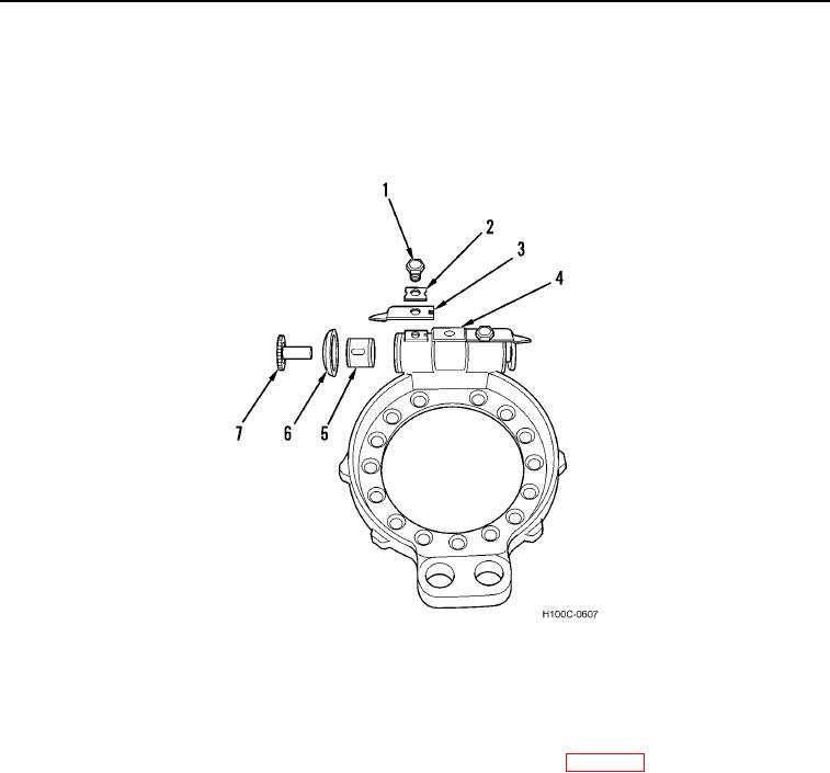
15. Bend back lock (Figure 6, Item 2) and remove bolt (Figure 6, Item 1).
16. Remove lock (Figure 6, Item 2) and detent (Figure 6, Item 3).
17. Remove adjustment bolt (Figure 6, Item 7) from plunger (Figure 6, Item 5).
18. Remove seal (Figure 6, Item 6) and plunger (Figure 6, Item 5) from plunger housing (Figure 6, Item 4).
Figure 6. Plunger Disassembly.
0059
END OF TASK
CLEANING AND INSPECTION
00059
1. Clean and inspect all components IAW General Maintenance Instructions (WP 0019).
2. Inspect wheel cylinder cup and plug for signs of wear or cracking. Replace if necessary.
3. Inspect wheel cylinder for scoring or damage. Replace if necessary.
4. Inspect parts of wedge and roller assembly and plunger assembly for signs of wear or damage. Replace if
necessary.
5. Inspect plunger seal. Replace if necessary.
6. Inspect anchor pins for wear or misalignment. Inspect brake shoes for wear at anchor pin holes. Replace if
necessary.
END OF TASK
0059-6

