
TM 5-3805-255-14
0059
BRAKE RELINING
00059
1. Remove rivets (Figure 7, Item 1) and linings (Figure 7, Item 2) from shoes (Figure 7, Item 3). Discard rivets.
NOTE
Lining and shoe contact faces should be clean before assembling. Rivets of the correct
size and shape must be used.
2. Clamp new lining (Figure 7, Item 2) to shoes (Figure 7, Item 3) so rivet holes in both pieces are aligned.
Figure 7. Brake Relining.
0059
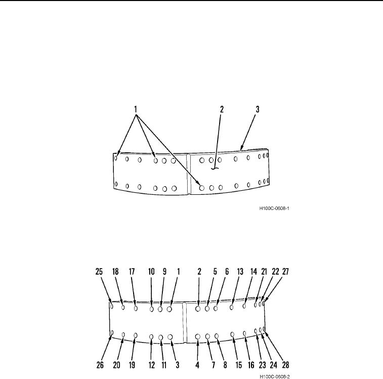
3. Install rivets in sequence shown in Figure 8.
Figure 8. Rivet Installation Sequence.
0059
4. Check lining installation with a 0.002-in. feeler gauge to assure proper lining and shoe contact.
END OF TASK
0059-7