
TM 5-3805-255-14
0060
ASSEMBLY CONTINUED
NOTE
Late model units are equipped with an indicator rod which is installed in place of the lower
right-hand bolt. Also, an external breather replaces the filter screen just below the lower
left-hand bolt.
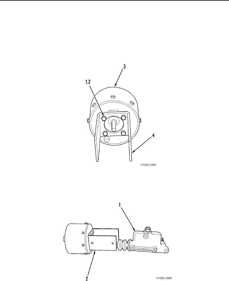
11. Install bracket (Figure 18, Item 4), four new lockwashers (Figure 18, Item 2), and bolts (Figure 18, Item 1) on
air cylinder (Figure 18, Item 3).
Figure 18. Bracket.
060
12. Install hydraulic cylinder (Figure 19, Item 1) on bracket (Figure 19, Item 2). Be certain plunger on air cylinder
fits in metal grommet in boot on hydraulic cylinder.
Figure 19. Hydraulic Cylinder.
060
0060-12