• Home
  • Download PDF
  • Order CD-ROM
  • Order in Print
Figure 13. Hydraulic Cylinder Assembly.
Figure 17. Return Spring.

Maintenance Manual For Loader, Scoop Type, Ded 4 X 4, Articulated Frame Steer, 4.5 To 5 Cu. Yd.
Page Navigation
  534    535    536    537    538  539  540    541    542    543    544  
img
TM 5-3805-255-14
0060
ASSEMBLY CONTINUED
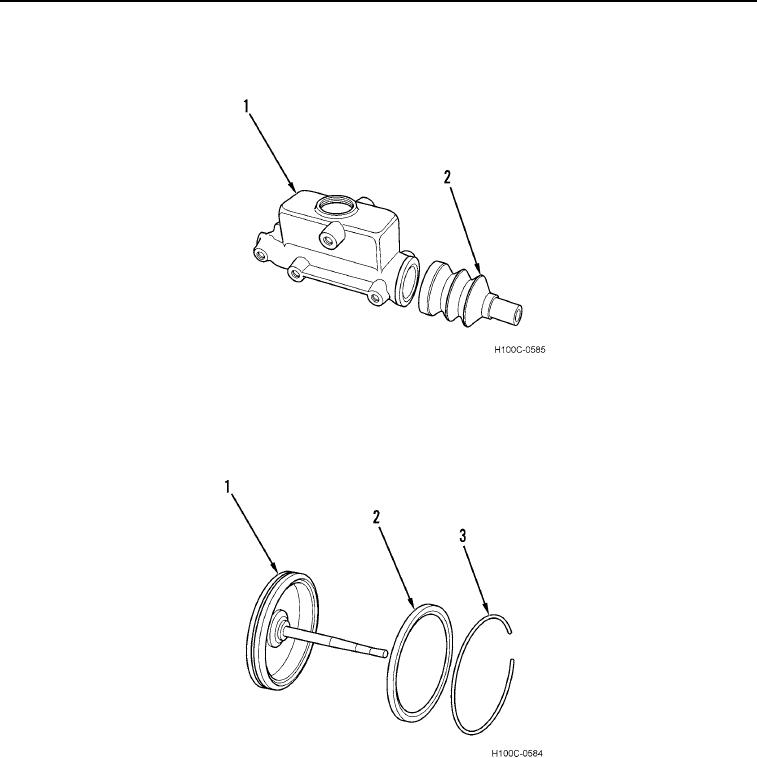
6. Install piston rod boot (Figure 14, Item 2) on hydraulic cylinder (Figure 14, Item 1).
Figure 14. Rod Boot.
060
7. Lubricate air cylinder piston cup (Figure 15, Item 2) and wiper (Figure 15, Item 3) with brake fluid and install on
piston (Figure 15, Item 1).
Figure 15. Piston Cup.
060
0060-10


Privacy Statement
Press Release
Contact

© Copyright Integrated Publishing, Inc.. All Rights Reserved.