
TM 5-3805-255-14
0078
ADJUSTMENT CONTINUED
5. Check valve discharge pressure. Continue to test and adjust relief valve pressure until recommended setting is
obtained. Always turn adjusting screw clockwise at least one-half turn to set preload.
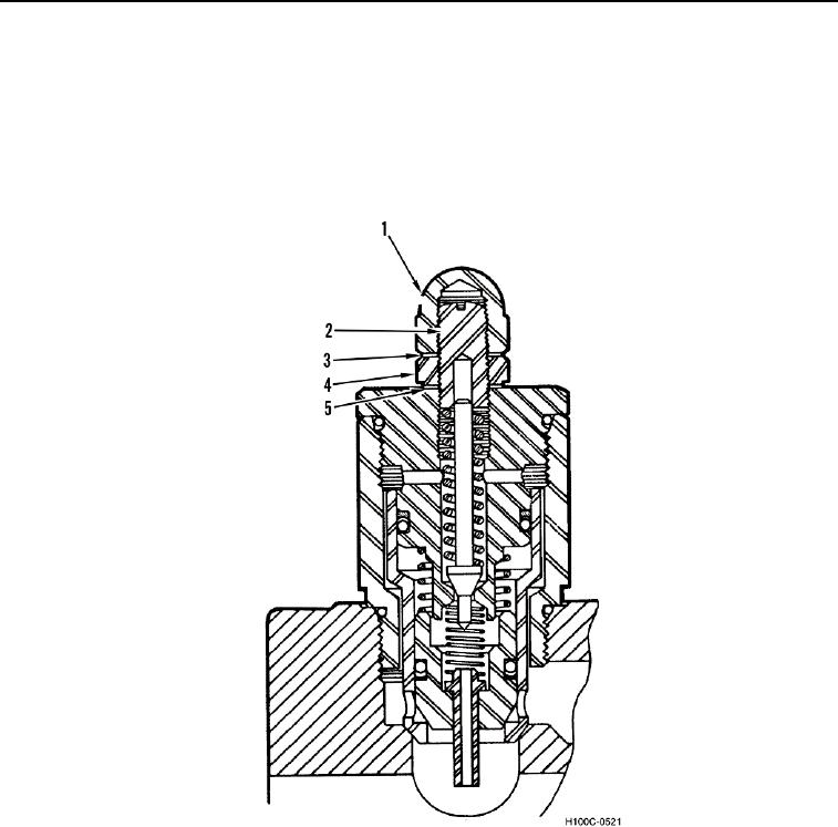
6. When correct adjustment is obtained, hold adjusting screw (Figure 9, Item 2) and tighten locknut (Figure 9,
Item 4).
7. Install copper washer (Figure 9, Item 3), if in good condition, and acorn nut (Figure 9, Item 1) on relief valve
(Figure 9, Item 5).
H100C-0521
Figure 9. Bucket Circuit Relief Valve.
0078
0078-11