
TM 5-3805-255-14
0080
REMOVAL
00080
NOTE
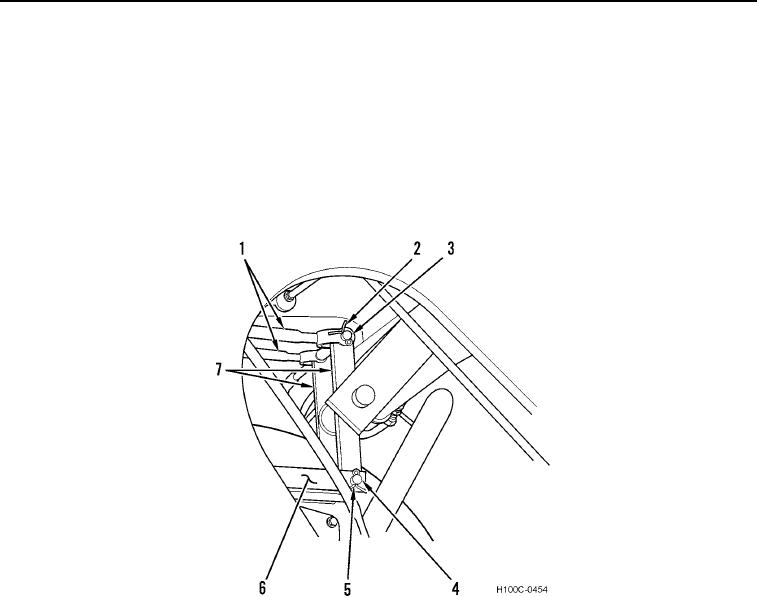
This procedure removes both control rods and linkages.
1. Remove two cotter pins (Figure 1, Item 2) from clevis pins (Figure 1, Item 3). Discard cotter pins.
2. Remove two clevis pins (Figure 1, Item 3) and control rods (Figure 1, Item 1) from bellcrank (Figure 1, Item 7).
3. Remove two cotter pins (Figure 1, Item 5) from clevis pins (Figure 1, Item 4). Discard cotter pins.
4. Remove two clevis pins (Figure 1, Item 4) and linkage (Figure 1, Item 6) from bellcrank (Figure 1, Item 7).
Figure 1. Hydraulic Control Linkage at Bellcrank.
0080
0080-2