
TM 5-3805-255-14
0078
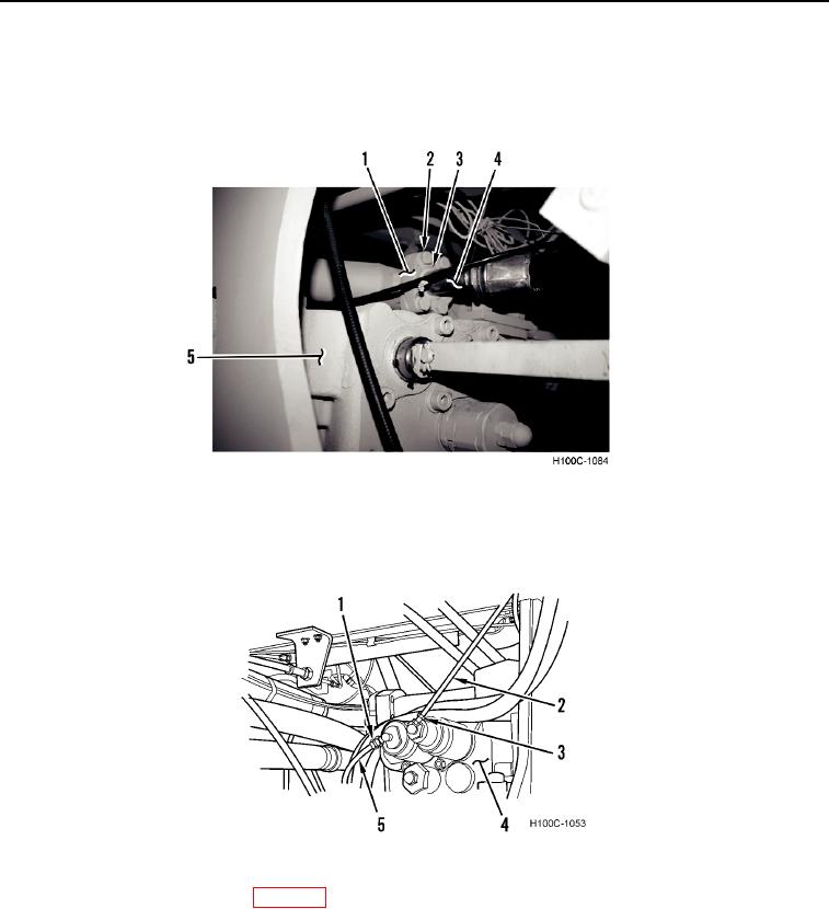
INSTALLATION CONTINUED
7. Install front hydraulic line (Figure 6, Item 4) on main control valve (Figure 6, Item 5).
8. Install new O-ring (Figure 6, Item 3), two split flanges (Figure 6, Item 1) and four machine bolts (Figure 6,
Item 2) on front hydraulic line (Figure 6, Item 4).
Figure 6. Side Hydraulic Lines.
0078
9. Install two lines (Figure 7, Items 2 and 5) on main control valve (Figure 7, Item 4). Tighten two fittings (Figure 7,
Items 1 and 3).
Figure 7. Gauge Lines.
0078
10. Fill reservoir with hydraulic oil (WP 0018).
11. Start engine and operate boom and bucket through several cycles to purge air from system. Adjust relief
valves. Refer to Adjustment in this work package.
END OF TASK
0078-6