
TM 5-3805-255-14
0086
REMOVAL CONTINUED
7. Back loader away from bucket.
CAUTION
In step 8, do not allow links to strike polished surface of tilt cylinder assembly rods. To do
so may cause damage to cylinder assemblies resulting in hydraulic oil leakage and
requiring replacement and repair of cylinder assemblies. Failure to follow this caution may
result in damage to the equipment.
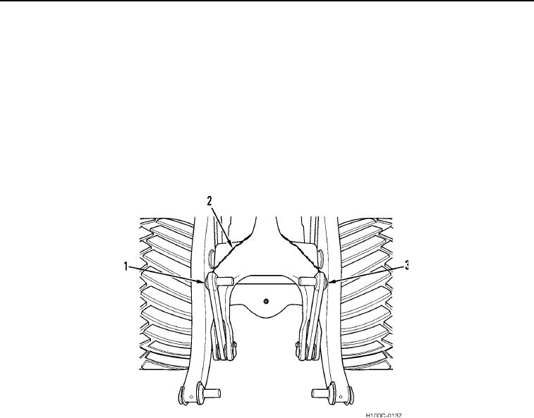
8. Swing links up and over bellcrank assemblies and secure in position so that they cannot move. Make sure that
links don't strike and damage polished surface of tilt cylinder assembly rods.
9. Use a heavy gauge wire (Figure 3, Item 2) to wire bucket links (Figure 3, Items 1 and 3) to top of bellcrank.
Figure 3. Bucket Links Wired Up.
0086
END OF TASK
00086
0086-3