
TM 5-3805-255-14
0086
INSTALLATION
00086
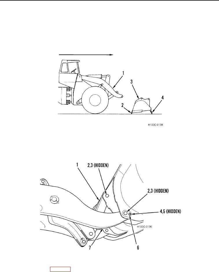
1. Position bucket (Figure 4, Item 3) on ground so it rests on cutting edge (Figure 4, Item 2) and spill guard
(Figure 4, Item 4).
2. Remove wire holding boom arms (Figure 4, Item 1) to loader. Discard wire.
3. Start engine. With engine running, raise and position boom arms (Figure 4, Item 1) so holes in arms are directly
in line with holes in bucket (Figure 4, Item 3).
Figure 4. Bucket Placement.
0086
4. Install four pins (Figure 5, Item 2), cord rings (Figure 5, Item 3), two locking capscrews (Figure 5, Item 4), new
lockwashers (Figure 5, Item 5), and flat washers (Figure 5, Item 6) on bucket (Figure 5, Item 1).
Figure 5. Bucket Installation.
0086
5. Test bucket operation (WP 0005).
END OF TASK
0086-4