
TM 5-3805-255-14
0089
REMOVAL CONTINUED
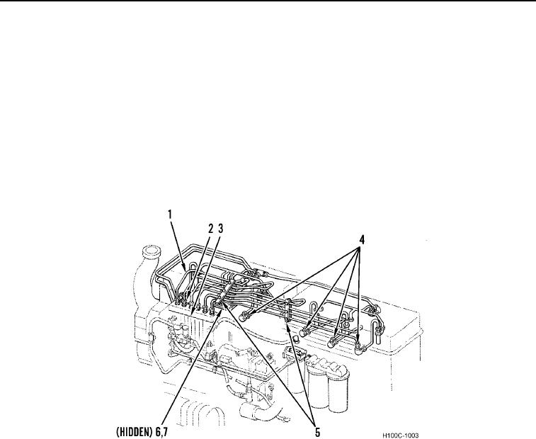
5. Disconnect fuel injection lines (Figure 3, Item 2) from fuel injection pump (Figure 3, Item 3).
6. Disconnect fuel injection lines (Figure 3, Item 2) from fuel injection pipes (Figure 3, Item 4).
NOTE
Do not remove fuel lines from injection pipe clamps and support brackets. Leave as an
assembly connected to brackets.
7. Remove two bolts (Figure 3, Item 6) and lockwashers (Figure 3, Item 7) from fuel line brackets (Figure 3,
Item 5). Discard lockwashers.
8. Remove fuel lines (Figure 3, Item 2) and brackets (Figure 3, Item 5) as fuel line assembly (Figure 3, Item 1).
9. Cap opening at injection pump, valve housings, and open ends of fuel lines.
Figure 3. Injection Pump Fuel Lines.
0089
0089-4