
TM 5-3805-255-14
0089
REMOVAL CONTINUED
CAUTION
Tag and identify all hose flanges for ease of installation. Cap all hoses to prevent
contamination and leaks. Failure to follow caution may result in failure of equipment.
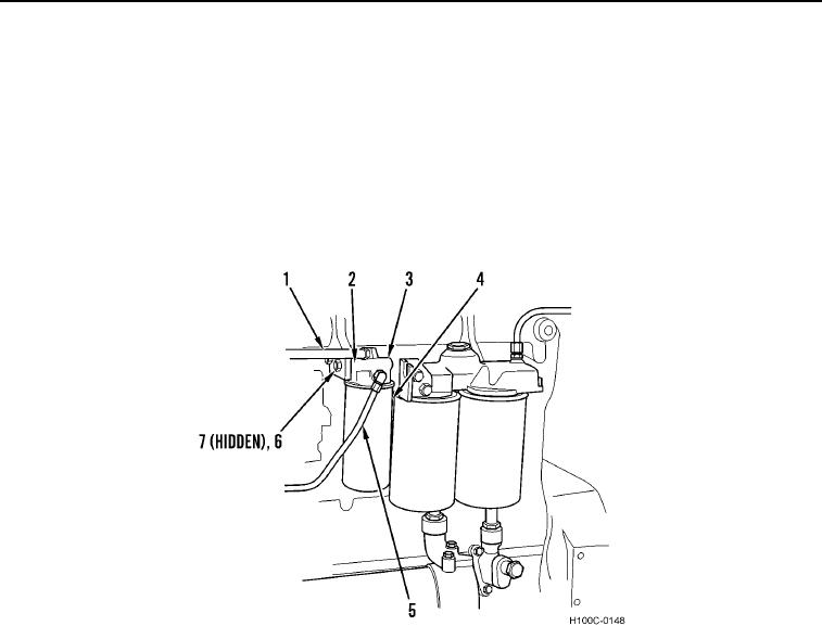
2. Disconnect injection pump hose (Figure 2, Item 1) and pump supply tube (Figure 2, Item 5) from final fuel filter
header (Figure 2, Item 3).
3. Remove two bolts (Figure 2, Item 6) and lockwashers (Figure 2, Item 7) from final fuel filter header (Figure 2,
Item 3) and final fuel filter support (Figure 2, Item 2). Discard lockwashers.
4. Remove final fuel filter (Figure 2, Item 4) and final fuel filter header (Figure 2, Item 3) from engine as an
assembly.
Figure 2. Final Fuel Filter and Connections.
0089
0089-3