
TM 5-3805-255-14
0089
REMOVAL CONTINUED
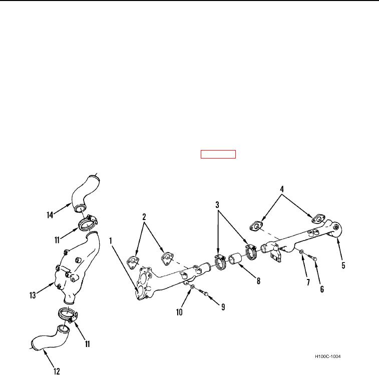
10. Remove two clamps (Figure 4, Item 3) on hose (Figure 4, Item 8) from front coolant manifold (Figure 4, Item 1)
and rear water manifold (Figure 4, Item 5).
11. Remove four bolts (Figure 4, Item 6), lockwashers (Figure 4, Item 7), rear coolant manifold (Figure 4, Item 5),
and two manifold gaskets (Figure 4, Item 4) from cylinder head. Discard lockwashers and gaskets.
12. Disconnect two hose clamps (Figure 4, Item 11), water outlet hose (Figure 4, Item 14), and by-pass hose
(Figure 4, Item 12) from thermostat housing (Figure 4, Item 13).
NOTE
Remove air compressor water inlet hose from thermostat housing (if equipped). Where
necessary, remove alternator brace bolt and washer from thermostat housing.
13. Remove six bolts (Figure 4, Item 9), lockwashers (Figure 4, Item 10), front coolant manifold (Figure 4, Item 1),
and two manifold gaskets (Figure 4, Item 2) from cylinder head. Discard lockwashers and gaskets.
14. Remove thermostat housing from front coolant manifold (WP 0037).
Figure 4. Coolant Manifolds.
0089
0089-5