TM 5-3805-255-14
0089
CLEANING, INSPECTION, AND REPAIR CONTINUED
Valve Lever and Lever Shaft Assembly
00089
1. Wash all parts in a cleaning solvent and dry thoroughly with compressed air. Be sure drilled oil passages in
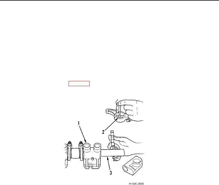
lever shaft (Figure 21, Item 3), intermediate brackets (Figure 21, Item 1), and lever bushings (Figure 21,
Item 2) are open. Also clean out oil passages in push rods.
2. Check outside diameter of valve lever shaft (Figure 21, Item 3) with a micrometer. Check inside diameter of
valve lever bushings (Figure 21, Item 2) with telescoping gauge. Difference between these two readings is
running clearance. If clearance is greater than 0.001 to 0.003 in. (0.03 to 0.08 mm) with a maximum allowable
clearance of 0.006 in. (0.15 mm), replace worn parts.
3. When replacing lever bushings (Figure 21, Item 2), be certain that oil hole in bushing aligns with oil hole in
lever. Bore or hone bushings to 1.4220 to 1.4235 in. (36.119 to 35.157 mm).
4. Inspect valve stem contact pad surface of valve levers and replace if wear is severe.
5. Remove and recondition valves (WP 0086).
Figure 21. Checking Valve Lever Bushing and Shaft for Wear.
0089
Injector Nozzle Lines
00089
Blow compressed air through injector nozzle supply and return lines to be sure they are clean.
END OF TASK
0089-21

