
TM 5-3805-255-14
0089
INSTALLATION CONTINUED
NOTE
With the following procedure, it is essential that thread lubricant be used where specified.
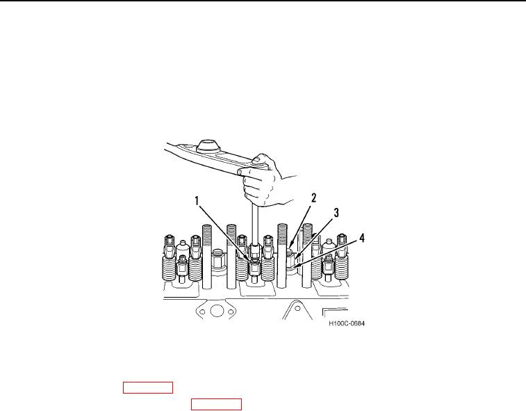
3. Apply thread lubricant at nut end of cylinder head studs (Figure 25, Item 2), both sides of flat washers
(Figure 25, Item 4), and nuts (Figure 25, Item 3) on all short cylinder head studs. DO NOT torque hardware.
4. Center stud (Figure 25, Item 1) may be equipped with special crab.
Figure 25. Torquing Injector Nozzle Crab Bolt.
0089
5. Install injector nozzles (WP 0027).
6. Connect fuel return and supply tubes (WP 0027).
0089-25