
TM 5-3805-255-14
0096
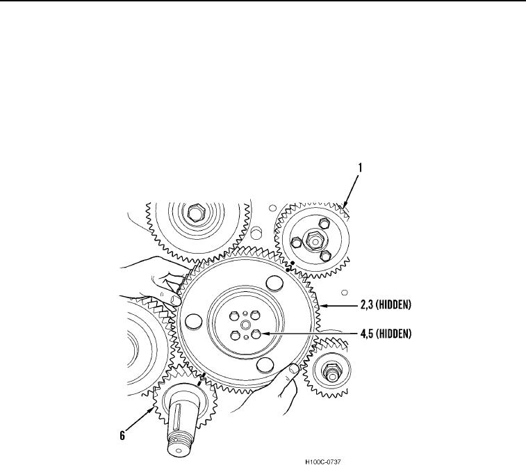
REMOVAL CONTINUED
6. Crank engine until timing marks on crankshaft gear (Figure 4, Item 6), camshaft gear (Figure 4, Item 2), and
injection pump drive gear (Figure 4, Item 1) are in line.
NOTE
If equipped with a lockplate, discard plate and replace with new capscrews and
lockwashers.
7. Remove four capscrews (Figure 4, Item 4), lockwashers (Figure 4, Item 5), and camshaft gear (Figure 4, Item
2) from camshaft (Figure 4, Item 3). Discard lockwashers.
Figure 4. Timing Marks Alignment.
0096
0096-4