Home
Download PDF
Order CD-ROM
Order in Print
Figure 4. Timing Marks Alignment.
Figure 6. Camshaft Removal.
Maintenance Manual For Loader, Scoop Type, Ded 4 X 4, Articulated Frame Steer, 4.5 To 5 Cu. Yd.
Page Navigation
896
897
898
899
900
901
902
903
904
905
906
TM
5-3805-255-14
0096
REMOVAL
CONTINUED
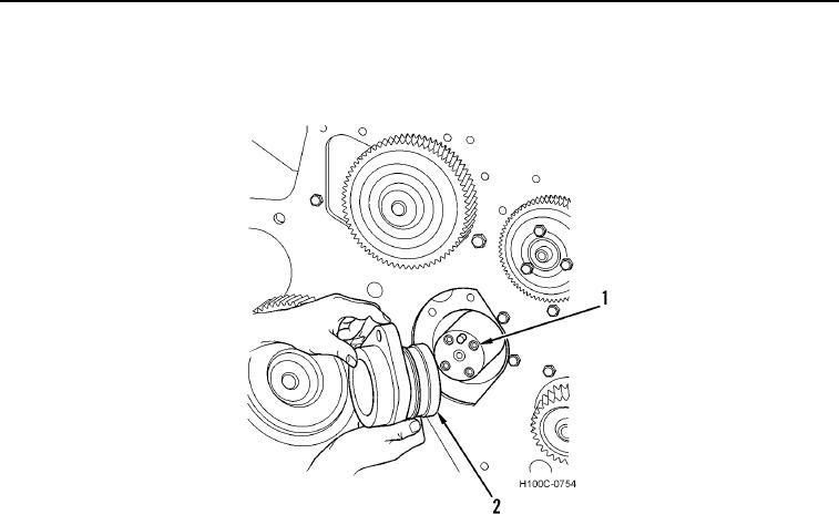
8.
Remove
five
capscrews,
lock,
and
camshaft thrust
bearing
hub
(Figure
5,
Item
2) from camshaft
(Figure
5,
Item
1).
Figure 5.
Camshaft
Thrust Bearing Hub Removal.
0096
0096-5